Variable Speed Drives and Their Interfaces
Human Machines Interfaces or HMIs are a vital part of variable speed drives today. HMIs can vary from the interface being a simple LED status indicator to a more complex field bus system with detailed VSD information. The HMI will set up an interface between a human and an application that will allow the user to control, monitor and diagnose the application.
More modern VSDs often have these HMI interfaces:
LED

An LED to indicate that power is applied to the VSD.
An LED to indicate that a warning is present
An LED to indicate an alarm on the FC.
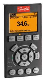
Numerical and/or Alphanumerical Panels

These devices provide an easy possibility to control the FC, monitor its actual status and for easy commissioning of the application.
Input and output control terminals are available in order to build an interface between a PLC control and the FC.
Input control signals like stop/start, coast or reverse control will ensure that the user has functions to control the FC according to the application. For controlling the speed, and feedback singles from the application analogue input signals like 0-10 V or 0/4-20mA can be applied.
Feedback signals from the VSD to the PLC are digital output or relay output which can be configured to indicate status like “motor running” or “alarm”. Also analogue output signals from the VSD can be configured to monitor, for instance, the actual load conditions.
software Tools
Integration of the VSD into the PC software gives the user full system configuration and control. With PC Software it it is possible to monitor the entire system more effectively for faster diagnosis, and better preventive maintenance.
A modern PC software tool can be used as follows:
Operating Principles of Serial Interfaces
- For planning a new communication network offline. PC Software tools contains a complete database with supported VSD products
- For commissioning VSDs online
- For easy replacement of a VSD, in the event of failure.
- For easy expansion of the network with more VSDs
- For back-up of parameter settings of VSDs in a communication network
- Software supports fieldbus protocol. This will eliminate the need for an extra communication network
Fieldbus
Use a standardised fieldbus interface between the PLC and VSD for commissioning, control and monitoring of the application.
Operating Principles of Serial Interfaces
In serial data transmission, the bits (with a state of 0 or 1) are transmitted individually, sequentially. A logical 0 or a logical 1 is defined by specified voltage levels. Various methods and standards have been developed to ensure fast, error-free data transfer. The method used depends on the specification of the interface. If we look at the lowest level of data transfer, a distinction can be made between how the bits are transmitted electrically (current or voltage signal) and the system used (line coding~). If the bits are transmitted via a voltage signal, the focus is less on the voltage level than the reference potential of the level.
RS-232/ EIA-232 interface
The RS-232 interface, launched as early as 1962, was for a long time the serial interface par excellence. When a serial interface was mentioned in relation to PCs, it referred to RS-232 was conceived for communication between two devices (point-to-point connection) at low transmission speeds.
RS-422 /EIA-422 interface
RS-422 allows both point-to-point and multi-drop networks to be built. In multi-drop networks, it is possible to connect multiple receivers to one transmitter. The data is transmitted differently via twisted data cables. One pair of lines is needed for each transmission direction for full duplex operation.
RS-485/EIA-485 interface
RS-485 is regarded as a higher-level version of the RS-422 standard and accordingly has similar electrical properties.
In contrast to RS-422, however, RS-485 is designed as a multi-point (bus-capable) interface over which up to 32 devices can communicate. There are now also transceiver modules (combined transmitter and receiver module) with which networks of up to 256 devices can be implemented. The actual maximum possible network size depends on both the transmission rate (line length) and the structure of the network (network topology).
USB interface
The Universal Serial Bus (USB) standard was developed in 1995 by intel in conjunction with companies in the IT industry. The USB 2.0 extension of the standard in 200 increased the transmission speed from 12 Mbps to 480 Mbps. Additionally, in 2008 USB 3.0 was introduced, allowing transmission speeds of up to 5 Gbitps. The data is Transmitted differentially via a twisted pair. The maximum cable length between two devices must not exceed 5 m.
Despite its name, USB is not a physical data bus, but rather a point-to-point interface. The term “bus” in the name USB refers only to the structure with which a network can be built. The USB specification provides for a central host (master) to which up to 127 different devices can be connected. Only one device can be connected directly to a port. An additional hub is required to connect more than one device to a port.
Ethernet interface
The ethernet standard was developed back in the early 1970’s. Since then Ethernet has become more and more present in all kinds of products. In the 90’s Ethernet found its way into the automation field via protocols like: MAP, Modbus TCP and EtherNet/IP. Ethernet typically runs on 100 Mbps, over STP cables (Shielded Twisted Pair), but is also available in wireless, fibre optic and other media. The benefit of using Ethernet is not only the fast speed and standardised cables and connectors, but the ability to access data inside automation equipment from the office network. This allows status to be read all over the plant, even from another continent.
Despite the fact that all Ethernet protocols run on Ethernet, it does not meat that it is possible to run different Ethernet technologies in the same network. Technologies that change the arbitration or have strict demands towards timing make a mix of technologies impossible. The mainstream Ethernet technologies today are PROFINET, EtherNet/IP, Modbus TCP, POWERLINK and EtherCAT. Today, these technologies have more than 90% of the market share in new installations.
Standard Serial Interfaces in Variable Speed Drives
Modern day VSDs are fitted as standard with a serial system interface that can be used for connection to a network.
Various standardised protocols are generally supported, in addition to unpublished, manufacturer-specific (proprietary) protocols. Physically, the interfaces are very often based on the specification of the RS-485 interface. Since VSDs usually only have a serial RS-485 interface available, interface converters are required for implementation. Manufacturer-specific solutions in which a particular VSD is required are widespread. If the interface specification is published, simple industry-standard converters (such as USB to RS-485) can be used.
VSDs are increasingly being fitted with USB interfaces for simple data exchange with a PC. Since many PC have USB interfaces, the use of interface converters is becoming obsolete.
Fieldbus Interfaces in Variable Speed Drives
The use of modern VSDs without a serial communication interface is almost inconceivable today. In the simplest case, the interface consists of two data lines through which the VSD can be controlled, monitored, configured and documented. Almost all bus systems enable multiple devices to be on the same network.
Compared with conventional VSD control via digital and analogue inputs and outputs, there is less cabling involved in serial bus systems, which reduced installation costs. On the other hand, costs are incurred for the interfaces and additional components are required to control the bus system. Depending on the bus system used, only a few networked devices are necessary to generate considerable cost benefits compared with conventional control.
Traditional wiring. No Fieldbus
In this type of network, communication between the drive and PLC requires one cable for each parameter that needs to be controlled. The advantage of such system is that the individual components themselves are relatively cheap, and the system itself is not the most complex. This, however, comes at a price, as such systems are relatively expensive both to install and extend, as each additional parameter or drive requires new cabling, PLC programming and often more I/O hardware. For owners this means higher capital costs and restricted flexibility. At the same time the risk of error is high, as the risk of a faulty connection to the PLC increases the number of cables.
Fieldbus Wiring
A typical fieldbus system only uses twisted pair cables to connect the drive to the PLC. Despite the higher cost of components, fieldbus systems offer several advantages over older, hardwired systems: fewer cables, faster commissioning and a reduced risk of faults.
Additional drives are connected in a serial Ethernet-based network that can be extended easily. New parameters only need to be coded into the PLC, which is both faster, safer and at significantly lower cost than hardwired system.
Fieldbus over Ethernet
The Ethernet interface enables the possibility to access drive parameters and information from locations outside the production facility. This method bypasses the traditional control hierarchy, as communication with the fieldbus-fitted drives and other equipment does not necessarily need to pass through the PLC. External access is routed through a firewall, enabling communication with the fieldbus option’s built-in webserver. Not only does this provide a high degree of flexibility during commissioning, it also provides provides advantages such as external monitoring and application support.
Fieldbus Standardisation
The development of fieldbuses began in the 1980s so that the benefits of serial communication could also be used in the field. The driving force for the development included not only the potential to save cost and time during planning and installation but also the ease of expansion and increased interference immunity when transmitting analogue signals.
In the years that followed, it became clear that the success of a system depends not only on the industrial capability in a demanding environment but also on “openness”. In open-bus systems, the installation and control are the same, irrespective of the manufacturer of the bus components. The end user can therefore replace a (defective) device from one manufacturer with a device from another manufacturer without having to make major changes to the system.
The principal difference between the interfaces and bus systems available on the market are the physical design and the protocols used. Which system is used depends on the requirements of the application in question.
Fast processes such as packaging machines may need bus cycle times of just a few milliseconds, whilst response times of seconds may suffice for climate control systems.
For the purposes of better classification, communication systems can be considered in terms of data volume, transfer time and transmission frequency. The diagram below shows the basic division into three different levels.
- At the company level, large data volumes in the megabyte range are exchanged. The transfer times can extend to hours
- At the cell level, the data volume decreases the kilobyte range. At the same time, the transfer time shortens (seconds) and frequency of data exchange (minutes/hours) rises
- At the field level, very small data volumes of a few bytes or even bits are exchanged. The transfer time and transmission frequency are a matter of milliseconds.
The world’s most important field buses have been standardised since 1999 in IEC 61158.
Different Bus systems have more or less significance depending on the region and application. If you look at drive technology, Profibus and its Ethernet based successor (PROFINET) can be considered to have a larger market share in in Europe. In contrast, DeviceNet and Ethernet/IP are frequently used in North and South America as well as in Asia. This defines the precondition for the high market acceptance of the respective Ethernet based successors PROFINET in Europe and EtherNet/IP in North America.
Northern Industrial can help with all of our drive interface and communication questions. Get in touch via our usual channels


